
ND Pico2DMX System
4-output Art-Net and sACN to DMX node with Ethernet, Wi-Fi, web dashboard
OVERVIEW
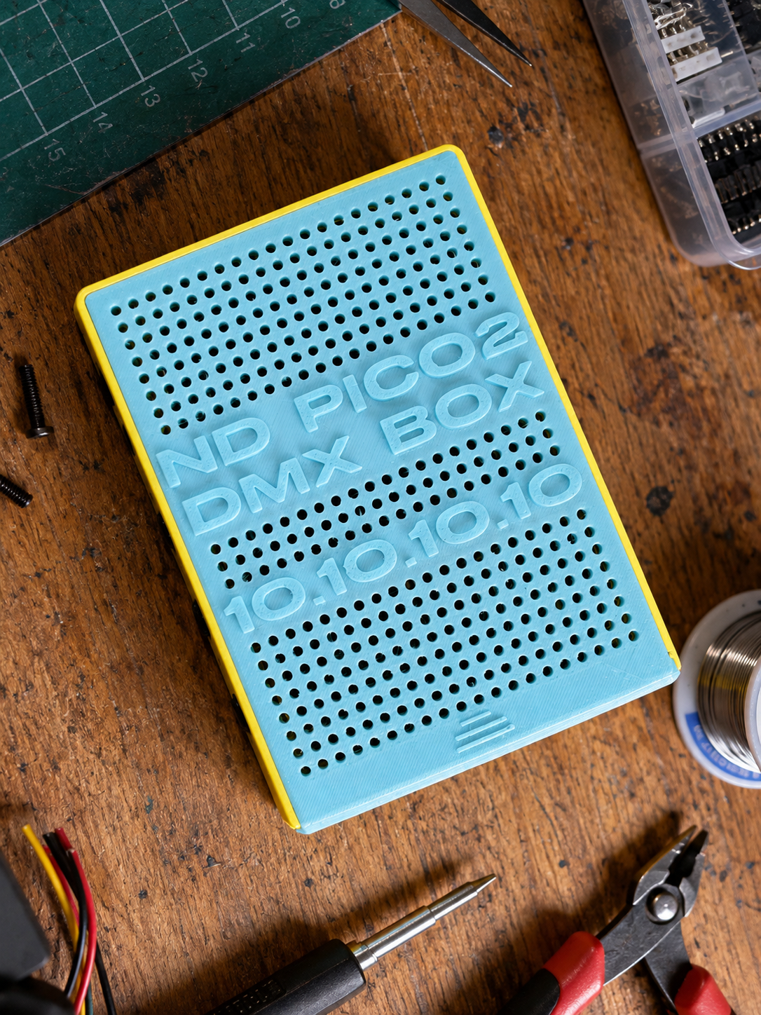
From a Small DIY Idea to a DMX Node I’d Actually Trust on a Job
ND Pico2DMX Node started with a pretty simple idea: I wanted to build my own network-to-DMX node.
I wanted something compact enough to carry around, stable enough to use in real lighting work, and flexible enough that I could understand and control every part of the system myself.
At the beginning, I wasn’t trying to build anything particularly complicated. I simply wanted to solve a practical problem in my own workflow.
But as the project grew, I started to realize that there is a huge difference between a prototype that works and a device that you are actually comfortable plugging into a real lighting system.
A lot of the development process ended up being about closing that gap.
And that journey involved quite a few redesigns, failed experiments, strange bugs, wiring problems, firmware mistakes, and many rounds of testing.
The beginning: RP2040 - W5500 and lot of wires
The first prototypes were built around an RP2040 with a separate W5500 Ethernet module.
On paper, the idea was straightforward.
The RP2040 would handle the main logic and DMX generation, while the W5500 would provide Ethernet connectivity. The node could receive Art-Net over the network, process the incoming data, and send it out through the DMX ports.
And it worked.
But as the prototype became more complete, a very practical problem started to appear:
there were simply too many wires.
Between the RP2040 board, the separate W5500 module, SPI connections, power, RS485 hardware and everything else around them, the project started to look more like a permanent electronics experiment on my desk than the foundation of a device I would actually want to build into an enclosure.
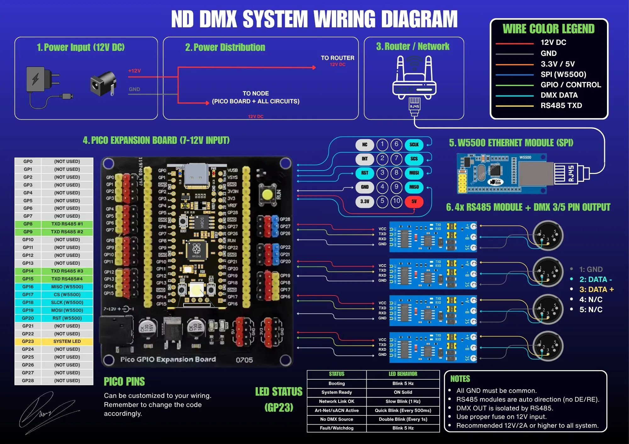
It wasn’t only about making things look cleaner, either.
Every additional wire is another possible connection problem. Every separate module means another connector, another solder joint, and another thing that needs to be checked when something stops working.
When you are developing firmware at the same time, this becomes particularly frustrating because every strange behavior raises the same question:
Is this a software problem, or is one of these wires causing it?
Eventually, I decided that instead of continuing to refine the original hardware, it made more sense to change the platform.
Moving to W5500 EVB Pico2 from Waveshare
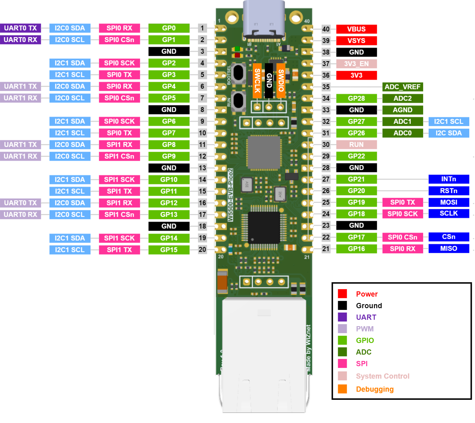
I moved the project to the Waveshare W5500-EVB-Pico2, which combines the RP2350-based Pico 2 platform with W5500 Ethernet in a much cleaner package.
That decision immediately made the project feel more focused.
Ethernet was no longer hanging off the main controller as a separate module. The amount of wiring was reduced considerably, hardware troubleshooting became easier, and the whole system started to look much more like something that could eventually become a proper device.
But moving from the RP2040 to the RP2350 wasn’t only about reducing wires.
I also wanted more room for the project to grow.
The current version of ND Pico2DMX Node provides four independent DMX outputs, but I was already thinking about a future 8-universe version while redesigning the hardware.
The additional resources available on the Pico 2 give me a much better foundation for that.
Instead of asking:
“Is this hardware powerful enough for what I need today?”
I started asking:
“What happens if I want this device to do twice as much in the future?”
That question ended up influencing quite a few architectural decisions later in the project.
Ethernet Wasn't Enough, I Still Wanted Wi-Fi
For a lighting node, Ethernet makes a lot of sense. It is stable, predictable, and when I’m working in a production environment, a wired connection is usually what I want.
But I also didn’t want the device to depend entirely on Ethernet.
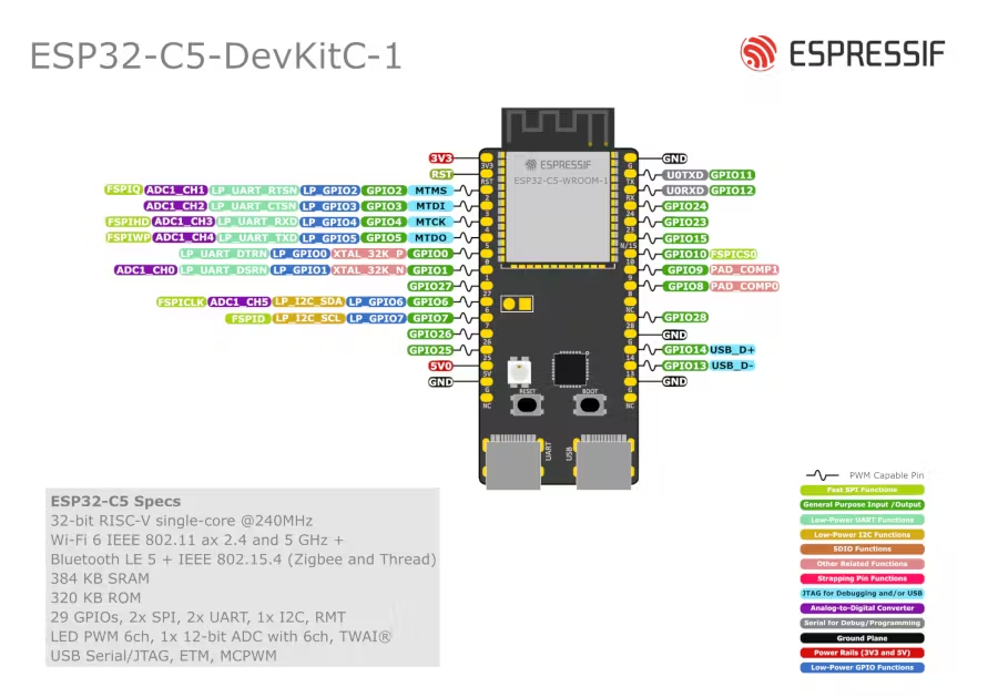
So I added an ESP32-C5 to handle the wireless side of the system.
The C5 can operate as its own Wi-Fi access point or connect to an existing wireless network, allowing the node to receive lighting data over Wi-Fi as well.
At this point, the architecture became a two-processor system.
The RP2350 acts as the main controller. It manages the core system, Ethernet side, system state and DMX outputs.
The ESP32-C5 handles Wi-Fi and acts as the gateway for lighting data arriving over the wireless network.
It sounds fairly straightforward when described like that.
Getting the two processors to communicate reliably, however, became one of the more interesting parts of the project.
Something "Can Work" Without Being the Right Solution
The first communication method between the RP2350 and ESP32-C5 was UART.
For small packets and basic testing, it worked perfectly well. At lower speeds, both processors could communicate reliably.
But DMX isn’t just a few status bytes sent every once in a while.
Once I started thinking about multiple universes of lighting data being transferred continuously, bandwidth became a real concern. Increasing the UART baud rate also started introducing reliability problems.
This became an important point in the project.
The easiest response would have been to keep trying to “fix UART.”
Instead, I decided to stop.
UART had already proved that the physical communication path between the processors worked. What it had also demonstrated was that it wasn’t the right transport for the amount of data I eventually wanted the device to handle.
So the interprocessor communication architecture was moved to SPI.
That decision became representative of an idea I kept coming back to throughout the project:
Just because something can be made to work doesn’t mean it should become part of the production architecture.
Sometimes the best solution to a problem isn’t another workaround.
Sometimes it is accepting that the original approach is no longer the right one.
And Then SPI Didn't Work Either
Of course, moving to SPI didn’t magically solve everything. At one point, SPI behaved very strangely.
The firmware looked correct. The pin mapping was checked. The SPI mode and clock were checked repeatedly. The protocol itself was reviewed. And yet the received data was still wrong.
This is exactly the kind of situation where it becomes very tempting to start changing everything at once.
Change the pins.
Change the clock.
Change the protocol.
Change the parser.
Change the timing.
The problem with doing that is that even if the system suddenly starts working, you may have no idea which change actually fixed it.
Eventually, the problem turned out to be much simpler: the physical interconnect.
After rewiring the complete connection between the two boards, including a proper ground connection, the same firmware, same pin mapping, same SPI mode and same clock suddenly behaved correctly.
That experience reinforced one of the most useful lessons from this project:
When debugging embedded hardware, don’t assume that every error appearing in a serial console must have been caused by software.
Sometimes the code was already correct.
DMX Had to Be Proven With Real Lights
Another rule I adopted during development was that I didn’t want to call a DMX output “working” just because a counter, console message or internal diagnostic said it was running.
DMX ultimately exists to control real equipment.
So the output chain was tested all the way through real hardware: from the node, through RS485 and wired DMX, through wireless DMX/CRMX, and finally to an actual fixture.
For part of this testing I used a Godox TimoLink TRX and an Aputure MC Pro, giving me a signal path much closer to the way I might actually use the device.
When the fixture responded correctly to FULL, BLACKOUT and real incoming network data, then I considered that output path proven.
The current version has four independent DMX outputs with their own output engines.
That architecture also gives me a foundation for the 8-output direction I want to explore in the future.
A Bug That Looked Like DMX, But Was Actually the Dashboard
One of the most interesting things about developing this project was discovering how often a bug could appear in a completely different part of the system from where it actually originated. At one point, the dashboard showed that Core 1 had stopped running and DMX output rates had dropped to zero.
The obvious suspects were the multicore logic, PIO code or DMX timing.
But after working through the system layer by layer, the major problem turned out to be somewhere very different:
the HTTP dashboard.
Some relatively large response buffers were being allocated locally inside functions.
On an embedded system with limited stack space, those buffers were large enough to corrupt memory around the stack, including memory associated with the other core.
From the outside, it looked like:
“The DMX engine crashed.”
But the DMX engine wasn’t actually the cause.
The buffers were moved into static storage and stack usage dropped dramatically. Core 1 and all four DMX outputs became stable again.
Of course, that fix introduced another HTTP bug because one piece of the buffer-size checking logic was still based on the old implementation.
So I fixed that too.
Importantly, I didn’t respond by rewriting the entire dashboard.
I isolated the new problem, made the smallest necessary correction, and tested everything again.
That gradually became the development philosophy of the project:
Change as little as possible at one time, understand what changed, and then verify the important parts of the system again.
The Dashboard Needed to Be for the Operator, Not the Firmware Developer
Early versions of the dashboard contained a lot of engineering information.
That was extremely useful during development, but eventually I realized that a production device shouldn’t require its operator to understand SPI counters, multicore diagnostics or internal debug values just to know whether everything is okay.
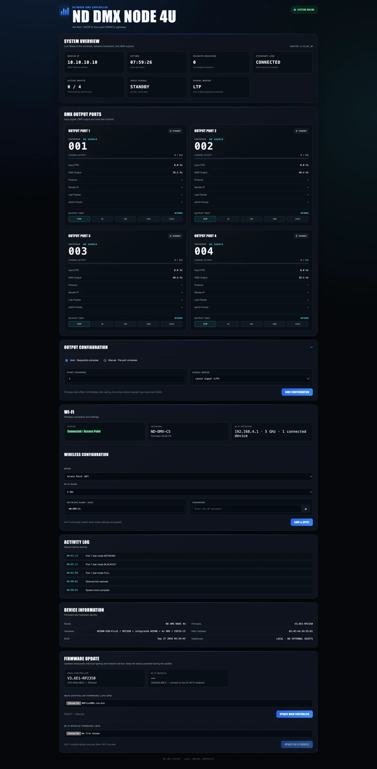
So the dashboard gradually became simpler.
An operator needs to know whether the network is connected, what the Wi-Fi is doing, whether the DMX outputs are running, which firmware version is installed, and what to do when updating the device.
The deeper engineering information is still available through the system API for troubleshooting, but it doesn’t need to be placed in front of the user all the time.
I particularly liked this stage of development because it represented a subtle change in the project.
It was no longer just: “a device I am debugging.”
It was starting to become: “a device somebody else could actually operate.”
Firmware update Became Their Own Little Adventure
OTA firmware updates took considerably more work than I originally expected.
The goal was simple: once the node was installed, I didn’t want to pull it apart and connect USB every time I needed to update the firmware.
So the RP2350 gained the ability to receive firmware updates directly through the Ethernet dashboard. The ESP32-C5 also has its own update workflow.
The first RP2350 OTA attempt failed.
Then the next one failed too.
At one stage the dashboard simply returned Not found.
Another time the firmware rejected an update even though the HTTP request appeared to be completely valid.
Another failure appeared to the browser as a lost connection, while the real problem was actually in the way the backend parsed the update confirmation header.
Each time, the most important thing was not to guess.
I inspected the actual request, OTA state, image size, flash layout, HTTP headers and every condition that occurred before the firmware started writing anything.
Eventually, one particularly stubborn problem came down to something almost comically small:
the expected length of an HTTP header name was wrong by one character.
One character.
That was enough to prevent the entire OTA process from starting correctly.
After correcting it and validating the process again, the controller successfully updated from F4 to F5 entirely through the Ethernet dashboard.
After rebooting, Ethernet came back, communication between both processors was healthy, Core 1 was running, all four DMX outputs were operating normally, and the physical FULL → BLACKOUT → NETWORK tests all passed.
That was the point where I considered Ethernet OTA truly finished.
Not when the code compiled.
Not when the upload progress reached 100%.
But when the controller updated itself, restarted, and continued controlling real lights correctly afterward.
“Stable” Doesn't Mean There Are No Bugs
One thing this project changed for me was the meaning of the word stable.
Stable doesn’t mean I believe the software contains no bugs.
It means I have a version where I know exactly what was tested, which hardware it was tested on, how it was connected, and what actually happened during those tests.
For ND Pico2DMX Node, the current production baseline uses RP2350 firmware V3.6F5 together with ESP32-C5 firmware V3.6A.
Once that baseline had been validated, I deliberately stopped “cleaning up” working code just because something could perhaps be written more elegantly.
I didn’t change DMX timing because another value looked theoretically nicer.
I didn’t refactor proven parts of the system simply because there was another way to implement them.
There is an important kind of discipline in embedded development:
knowing when not to change something that has already been proven to work.
What I Like Most About This Project
The thing I like most about ND Pico2DMX Node isn’t really one particular feature.
It’s the way the project came together.
A lot of things didn’t work on the first attempt.
UART didn’t become the final transport.
SPI once made us question the firmware when the real problem was the wiring.
A dashboard memory issue could stop the DMX core.
A single character in an HTTP parser could prevent the entire OTA process from working.
But each problem made the architecture a little clearer.
Throughout the project, I tried not to solve problems by changing five things at once. Instead, the process became: observe, verify, isolate, make the smallest reasonable change, and then test again on real hardware.
Some firmware versions looked perfectly fine on paper but weren’t considered finished because I hadn’t yet seen a real fixture respond correctly.
Some pieces of code could probably be refactored into something prettier, but were intentionally left alone because they had become part of a hardware-validated baseline.
And sometimes the right decision was to abandon an approach that had already taken a lot of work, like UART, because a different architecture was simply more appropriate.
That process is probably what I’m most proud of.
This Isn't the End
ND Pico2DMX Node now has a foundation that I feel comfortable calling v1.0.0.
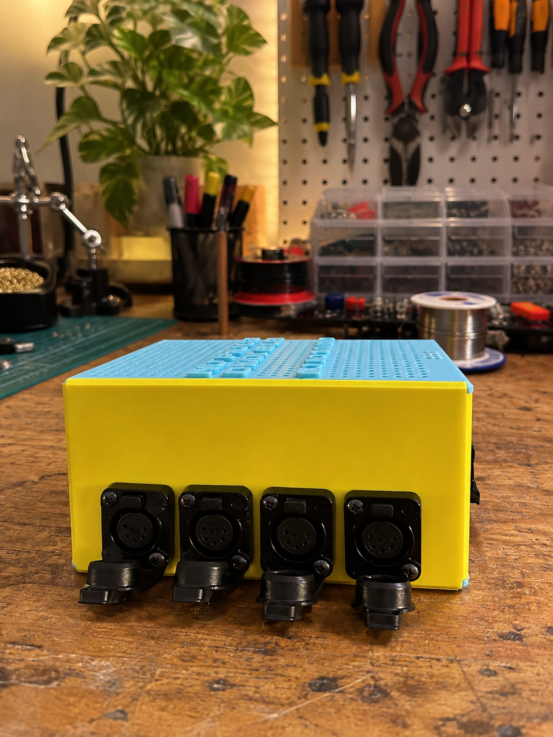
It provides Ethernet, Wi-Fi, Art-Net, sACN, four independent DMX outputs, a management dashboard, firmware updating, and a dual-MCU architecture where each processor has a clearly defined role.
But I never designed the project with only four outputs in mind.
Moving to the Pico 2 gives me room to explore an 8-universe version, more refined custom hardware revisions, and other ideas that I deliberately didn’t want to squeeze into v1.0.0 simply for the sake of having more features.
When those ideas become part of the project, I want to approach them the same way the current version was built:
Build one piece at a time. Understand why it works. Test it on real hardware. And don’t call it finished until I actually trust it.
ND Pico2DMX Node started with a few development boards, a lot of jumper wires, and the thought:
“I think I can build this myself.”
After a lot of builds, flashes, failed tests, debugging sessions, rewired connections, tiny code changes and starting the test again from the beginning, it has become something I would genuinely want to keep in my own lighting toolkit.
And for me, that’s probably the most rewarding part of building something yourself.
Frequently Asked Questions
Quick answers to frequently asked questions about the ND Pico2DMX Node
At the moment, ND Pico2DMX Node is primarily a personal and open-source project, created from a practical need in my own lighting workflow.
The goal wasn't simply to make a prototype capable of outputting DMX. I wanted to build something stable, understandable and structured well enough that I could continue developing it over time.
The current v1.0.0 design provides four independent DMX outputs, Ethernet and Wi-Fi connectivity, Art-Net and sACN support, a management dashboard and firmware updating.
The architecture has also been developed with future expansion in mind, particularly the possibility of an 8-universe version.
Whether it eventually develops beyond a personal/open-source project is something I'll decide as the hardware and project continue to evolve.
Yes. One of the reasons I made the project public is so that other people interested in lighting, embedded systems and DIY hardware can study it, build it and adapt it for their own projects.
For example, the GPIO mapping used for the DMX outputs can be changed when designing custom hardware, provided the developer understands the hardware resources involved and validates the new configuration properly.
There is, however, an important distinction between the official hardware configuration that I have personally tested and a custom build.
Once you change the hardware, GPIO mapping, output architecture or other fundamental parts of the design, that configuration should be treated as a new build that needs its own testing. It shouldn't automatically be assumed to have the same validation as the reference configuration.
That's also why I try to clearly document which parts of ND Pico2DMX Node have been proven on real hardware and which areas are intended for future development.
Yes. ND Pico2DMX Node is released under the GNU General Public License version 3 (GPLv3), using the GPL-3.0-only designation.
This allows you to use, study, modify and redistribute the covered software under the terms of the GPLv3.
If you distribute a modified version or a product containing software covered by the project's GPL license, you will need to comply with the applicable GPLv3 requirements, including the relevant source-code availability and license-notice obligations.
Some third-party libraries or components used by the project may also have their own licenses, and those licenses still need to be respected.
In simpler terms: you're welcome to learn from it, build it, modify it and create your own version - just make sure you follow the open-source license terms that come with the project.